
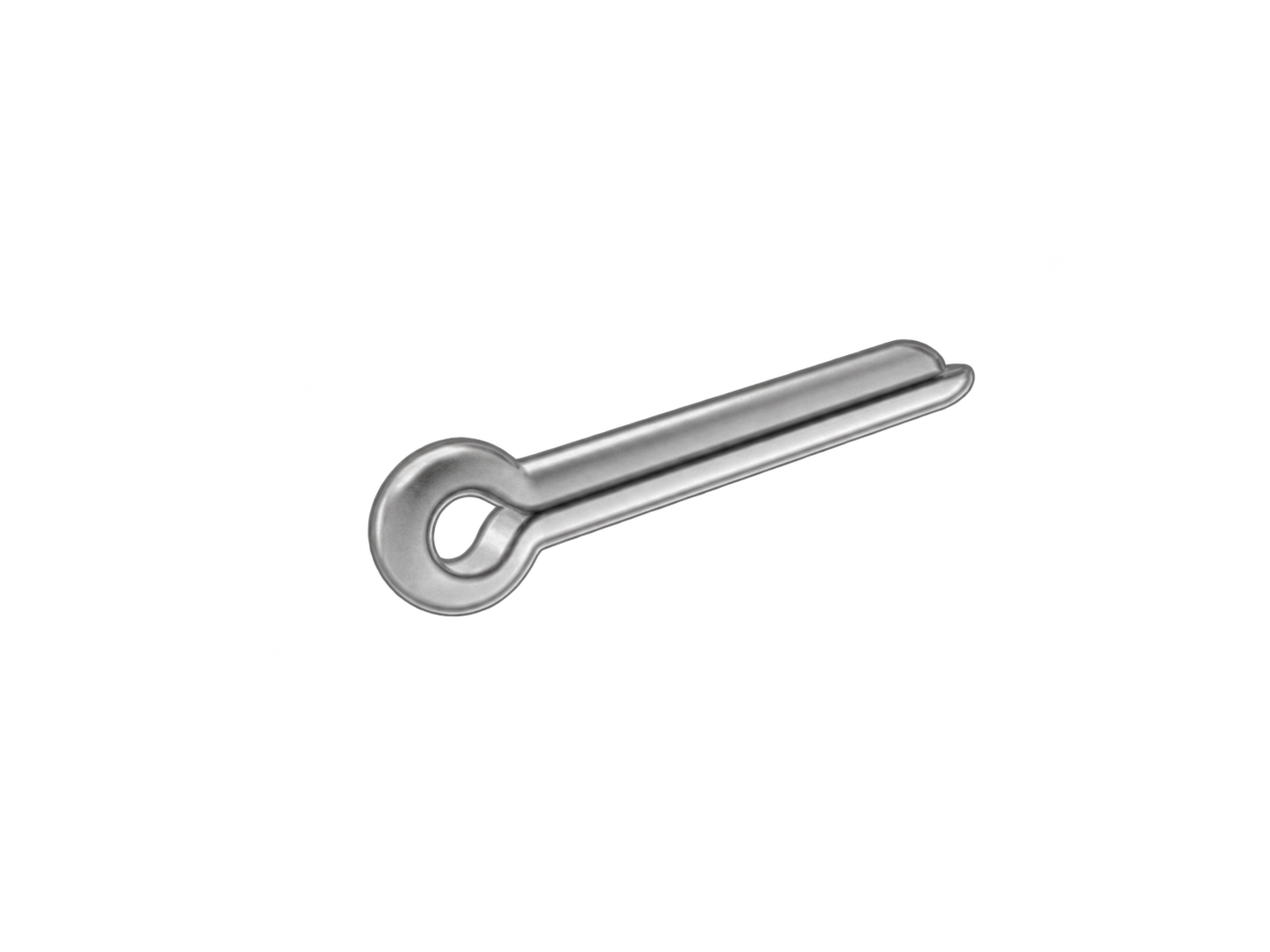
Pins

Split Pins

GB/T 91-2000 (reference only)

Request a quote ↗

GB/T 91-2000 dimension drawing

Dimensions in mm
GB/T 91-2000 dimension drawing

Specification parameters

Technical conditions and referenced standards

Material
  • Carbon steel: Q215 or Q235 (GB/T 700);
  • Copper alloy: H63 (GB/T 5232);
  • Stainless steel: 1Cr17Ni7 or 0Cr18Ni9Ti (GB/T 1220);
  • Other materials shall be agreed between the purchaser and supplier.
  • Carbon steel: Q215 or Q235 (GB/T 700);
  • Copper alloy: H63 (GB/T 5232);
  • Stainless steel: 1Cr17Ni7 or 0Cr18Ni9Ti (GB/T 1220);
  • Other materials shall be agreed between the purchaser and supplier.
Toughness
  • Each leg of the split pin shall withstand one complete bend cycle without fracture or cracking at the bend.
    Bend test: spread the split pin and clamp the straight portion of either leg in the test fixture without flattening it. Bend the pin through 90° and return it to its original position to complete one cycle. The test speed shall not exceed 60 cycles/min. The fixture shall have a semicircular groove with a diameter equal to the nominal pin size. The jaws shall have a corner radius of r = 0.5 mm.
  • Each leg of the split pin shall withstand one complete bend cycle without fracture or cracking at the bend.
    Bend test: spread the split pin and clamp the straight portion of either leg in the test fixture without flattening it. Bend the pin through 90° and return it to its original position to complete one cycle. The test speed shall not exceed 60 cycles/min. The fixture shall have a semicircular groove with a diameter equal to the nominal pin size. The jaws shall have a corner radius of r = 0.5 mm.
Workmanship
  • ① The eye shall be as nearly circular as practicable.
    ② The cross-section of the two legs shall be circular. A radius of r = (0.05–0.1)dmax is permitted where the flat faces meet the curved surface.
    ③ The gap and offset between the two legs shall not exceed the difference between the nominal pin size and dmax.
    ④ Split pins may be supplied with the legs spread apart (α is the angle between the inner flat faces
    ); nominal size ≤ 1.6 mm: α ≤ 8°; 2–6.3 mm: α ≤ 4°; ≥ 8 mm: α ≤ 2°
  • ① The eye shall be as nearly circular as practicable.
    ② The cross-section of the two legs shall be circular. A radius of r = (0.05–0.1)dmax is permitted where the flat faces meet the curved surface.
    ③ The gap and offset between the two legs shall not exceed the difference between the nominal pin size and dmax.
    ④ Split pins may be supplied with the legs spread apart (α is the angle between the inner flat faces
    ); nominal size ≤ 1.6 mm: α ≤ 8°; 2–6.3 mm: α ≤ 4°; ≥ 8 mm: α ≤ 2°
Surface discontinuities
  • Burrs and irregular or detrimental defects are not permitted.
  • Burrs and irregular or detrimental defects are not permitted.
Surface treatment
  • Steel;
  • Copper and stainless steel
  • Steel;
  • Copper and stainless steel
  • No treatment;
  • Zinc plating and passivation in accordance with GB/T 5267;
  • Phosphate coating in accordance with GB/T 11376
  • Simple treatment
Other coatings or surface treatments shall be agreed between the purchaser and supplier. Other coatings or surface treatments shall be agreed between the purchaser and supplier.
Acceptance inspection and packaging
  • GB/T 90
  • GB/T 90

Product overview

A split pin for retaining compatible fasteners or assemblies. Specify the nominal diameter and length.

For a quote, share the required dimensions, material, finish and quantity. Availability and lead time are confirmed for each enquiry.